
Designing a GPS tracker may look simple at first. You select a GPS module, connect an antenna, and then upload the location data through 4G, LoRa, or another communication network.
However, once the project enters the real hardware development stage, it becomes clear that the overall performance of a GPS tracker is not determined by a single module.
The final positioning speed, battery life, communication stability, production cost, and long-term reliability are all affected by the complete BOM and hardware architecture.
A GPS tracker may use the same positioning technology but still perform very differently depending on the selected:
- GNSS module
- MCU
- Cellular communication module
- LoRa module
- Antenna
- Power management IC
- Battery
- Sensors
- PCB materials
- Mechanical enclosure
Therefore, component selection for a GPS tracker should consider multiple factors at the same time, including:
- Positioning performance
- Power consumption
- Network coverage
- Battery life
- PCB size
- Antenna space
- Operating temperature
- Waterproof protection
- Product lifetime
- Supply chain stability
- Certification requirements
- Total BOM cost
This guide explains how to select the main components of a GPS and GNSS tracking device from a practical hardware development perspective.
1. Define the GPS Tracker Application First
Before selecting any electronic components, the first step is not to choose a GNSS chipset.
The first step is to clearly define where and how the product will be used.
Different applications require completely different hardware architectures.
Vehicle GPS Tracker
Vehicle GPS trackers are usually powered directly by the vehicle electrical system.
Therefore, power consumption is normally less critical than in battery-powered devices.
The hardware design should focus more on:
- Stable GNSS positioning
- Reliable 4G communication
- Wide input voltage
- ACC ignition detection
- Overvoltage protection
- Reverse-polarity protection
- Surge protection
- Temperature resistance
- Continuous online operation
For this type of product, a higher-performance GNSS module and cellular communication module can usually be selected.
Asset GPS Tracker
Asset tracking devices are often battery-powered.
Some applications require the tracker to operate for one, three, or even five years without charging.
For these products, ultra-low power consumption becomes one of the most important design targets.
The component selection may focus on:
- Ultra-low-power MCU
- Low-power GNSS module
- LTE Cat.1 bis
- LTE-M
- NB-IoT
- LoRa or LoRaWAN
- Hardware power switching
- MOSFET-controlled module shutdown
- High-capacity primary batteries
- Low self-discharge batteries
An asset tracker and a vehicle GPS tracker should not use the same component selection strategy.
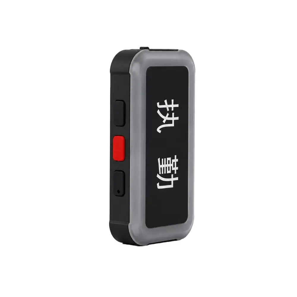
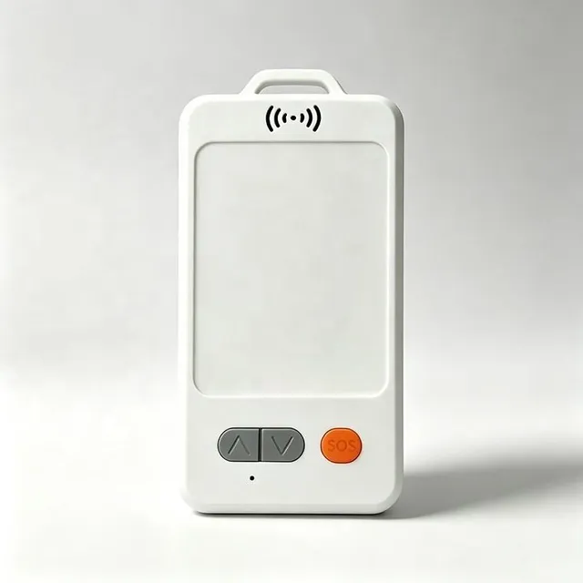
Personnel GPS Tracking Badge
Personnel tracking badges normally have stricter requirements for:
- Small size
- Lightweight design
- Fast positioning
- Indoor and outdoor positioning
- SOS button
- Bluetooth
- Wi-Fi scanning
- Fall detection
- Battery safety
- Rechargeable battery management
The hardware engineer must balance GNSS, BLE, Wi-Fi, 4G, sensors, and battery capacity within a limited enclosure size.
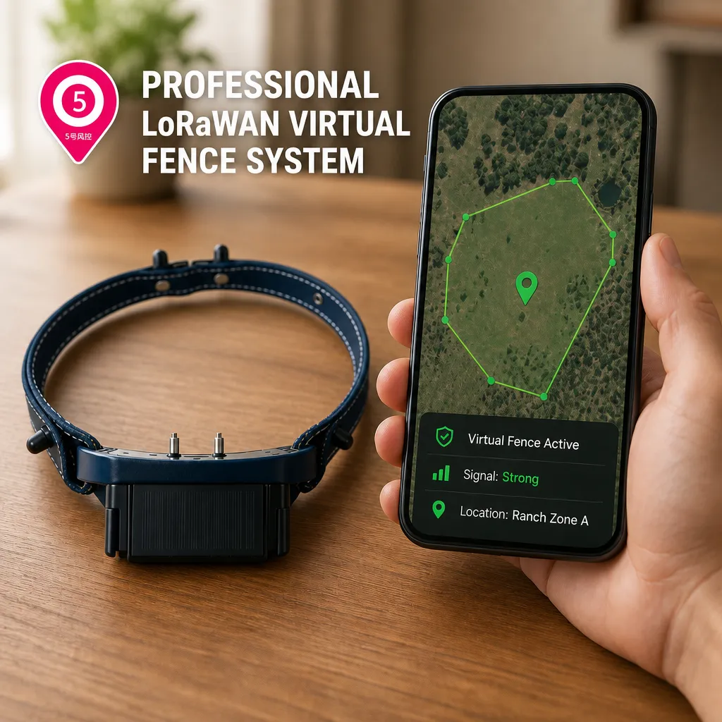
Livestock GPS Collar
GPS collars for cattle, sheep, and horses are mainly used outdoors.
The hardware design should therefore focus on:
- GNSS sensitivity
- Antenna orientation
- Waterproof protection
- Impact resistance
- Operating temperature
- Large battery capacity
- Solar charging
- LoRa or 4G communication
- Long-term outdoor reliability
Some virtual fencing collars may also include:
- Sound warning
- Electric pulse output
- Vibration
- IMU activity monitoring
For this reason, the application environment must be defined before the BOM is created.
2. How to Select a GNSS Module
The GNSS module is one of the most important components in a positioning device.
Modern positioning modules usually support more than GPS alone.
Common satellite systems include:
- GPS
- BeiDou
- GLONASS
- Galileo
- QZSS
For this reason, the term GNSS module is often more accurate than GPS module.
When selecting a GNSS module, several technical parameters should be evaluated.
3. GNSS Sensitivity
GPS tracking devices are often used in difficult environments such as:
- Urban areas with tall buildings
- Inside vehicles
- Near metal structures
- Near containers
- Under livestock body obstruction
- Semi-indoor environments
- Warehouses
GNSS sensitivity therefore has a major impact on actual positioning performance.
Important parameters include:
Tracking Sensitivity
Tracking sensitivity describes how well the GNSS receiver can continue tracking satellites after a position has already been acquired.
Acquisition Sensitivity
Acquisition sensitivity indicates how effectively the GNSS receiver can search for satellites when positioning starts.
Cold Start TTFF
TTFF means Time to First Fix.
Cold start TTFF refers to the positioning time when the device has little or no valid satellite data stored.
Hot Start TTFF
Hot start TTFF refers to the positioning time when the receiver still has useful satellite information available.
For low-power GPS trackers, TTFF is especially important.
If one device requires 30 seconds to obtain a position while another only requires 5 seconds, the difference can have a major impact on battery life.
4. Single-Frequency or Dual-Frequency GNSS?
Most ordinary GPS trackers can use single-frequency GNSS.
Typical applications include:
- Vehicle tracking
- Asset tracking
- Pet tracking
- Personnel tracking badges
- Livestock tracking
In open outdoor environments, meter-level positioning accuracy is usually sufficient for these applications.
For more demanding applications, dual-frequency GNSS can be considered.
Common frequency combinations include:
- L1 + L5
- L1 + L2
Dual-frequency GNSS can provide better positioning performance in urban environments and reduce some multipath errors.
If centimeter-level positioning is required, the product may need:
- RTK GNSS
- RTCM correction data
- NTRIP service
- Local base station
- CORS network
However, RTK should not be used in every GPS product.
RTK increases:
- Hardware cost
- Power consumption
- PCB complexity
- Antenna requirements
- Firmware complexity
- Server complexity
The GNSS solution should always match the actual product requirement.
5. How to Select a GPS Antenna
Many GPS positioning problems are caused by antenna design rather than the GNSS chipset.
A high-performance GNSS receiver can still perform poorly if the antenna is incorrectly selected or placed.
Typical problems include:
- Slow positioning
- Low satellite count
- Position drift
- Poor indoor performance
- Significant performance loss after assembly
Common GNSS antenna types include the following.
Ceramic Patch Antenna
A ceramic patch antenna usually provides stable positioning performance.
Advantages:
- Stable RF performance
- Good gain
- Relatively easy to tune
Disadvantages:
- Larger physical size
- Requires correct orientation
Typical applications include:
- Vehicle GPS trackers
- Livestock GPS collars
- Industrial trackers
- Asset trackers
FPC Antenna
FPC means Flexible Printed Circuit antenna.
Advantages:
- Thin profile
- Flexible installation
- Can be attached inside the enclosure
Disadvantages:
- Performance is easily affected by batteries, PCBs, and metal components
Typical applications include:
- GPS badges
- Pet GPS trackers
- Compact wearable devices
PCB Antenna
A PCB antenna can be integrated directly into the circuit board.
Advantages:
- Lower BOM cost
- No separate antenna component
Disadvantages:
- Higher PCB design requirements
- Structural changes may require retuning
PCB antennas are suitable for mass-production products with a stable mechanical design.
6. Why GPS Antenna Placement Matters
GNSS signals received from satellites are extremely weak.
Therefore, the GNSS antenna should be kept away from:
- Large metal parts
- Batteries
- 4G main antennas
- DC-DC inductors
- High-frequency clocks
- Displays
- Motors
- Speaker magnets
One very common hardware problem is:
The bare PCB performs well during testing, but GPS performance becomes poor after the PCB is installed inside the enclosure.
In many cases, the GNSS module has not changed.
The antenna environment has changed.
For this reason, RF testing should always be performed on the complete assembled product, not only on the bare PCB.
7. How to Select the MCU
The MCU is the main controller of the GPS tracker.
It typically controls:
- GNSS module
- 4G module
- LoRa module
- Position data processing
- Sensors
- Battery measurement
- Sleep mode
- Wake-up logic
- Communication protocols
- OTA firmware update
Important MCU parameters include:
- Flash memory
- RAM
- UART interfaces
- SPI
- I2C
- ADC
- GPIO
- RTC
- Watchdog
- Stop current
- Standby current
For ultra-low-power GPS trackers, deep sleep current is especially important.
For example, the difference between:
1 mA
and
5 μA
may look small during a short bench test.
However, for a device that must operate for several years, this difference can dramatically affect battery life.
8. How to Select a 4G Communication Module
Modern GPS trackers increasingly use 4G networks.
Common cellular technologies include:
- LTE Cat.1
- LTE Cat.1 bis
- LTE-M
- NB-IoT
The correct technology depends on the target market and application.
For global products, engineers should confirm support for regional LTE bands.
Different markets may require bands such as:
- B1
- B2
- B3
- B4
- B5
- B7
- B8
- B12
- B13
- B17
- B20
- B28
- B66
A product should never be defined only as supporting “4G.”
The exact LTE bands must be verified.
The design should also consider:
- SIM interface
- eSIM
- Antenna matching
- RF certification
- CE
- FCC
- Carrier certification
Otherwise, a tracker may work correctly in one country but fail to connect in another.
9. When Should LoRa Be Used?
Not every GPS tracker needs a cellular network.
For applications such as:
- Large farms
- Ranches
- Mining areas
- Industrial parks
- Factories
- Ports
- Warehouses
customers may deploy their own private gateways.
In these cases, the tracking device can use:
GPS + LoRa
or
GNSS + LoRaWAN
This architecture can reduce SIM card costs and cellular service fees.
LoRa can also provide significant power consumption advantages for battery-powered tracking devices.
Therefore, one of the first product decisions should be whether the tracker will use:
- Public cellular networks
- Private LoRa networks
- Hybrid communication
10. How to Select the Power Management IC
Many GPS tracker reliability problems are actually power supply problems.
A typical tracking device may contain:
- MCU
- GNSS
- 4G
- LoRa
- BLE
- Wi-Fi
- IMU
These components do not have the same power requirements.
Cellular modules in particular may require high peak current during transmission.
If the power supply design is insufficient, common problems may include:
- 4G disconnection
- Cellular module reset
- MCU crash
- GNSS data errors
- Sudden battery voltage drop
The selected DC-DC converter or LDO should therefore provide enough current margin.
Important parameters include:
- Conversion efficiency
- Quiescent current
- Output ripple
- Thermal performance
- Maximum output current
- PCB area
For low-power GPS trackers, quiescent current is especially important.
11. How to Select the Battery
The battery is one of the most important parts of the GPS tracker BOM.
Common battery options include the following.
Lithium Polymer Battery
Suitable for:
- GPS personnel badges
- Pet GPS trackers
- Rechargeable asset trackers
Advantages include:
- Compact size
- High energy density
- Rechargeable operation
18650 or 21700 Battery
Suitable for:
- High-capacity asset trackers
- Livestock GPS trackers
- Solar-powered devices
Advantages include:
- Large capacity
- Mature supply chain
- Good availability
Li-SOCl2 Battery
Li-SOCl2 means lithium thionyl chloride battery.
It is commonly used in:
- Ultra-long-life asset trackers
- Battery-powered IoT devices
- Low-duty-cycle GPS trackers
Main advantages include:
- Very low self-discharge
- High energy density
- Long service life
However, pulse current capability must be carefully evaluated.
Cellular modules may require assistance from:
- Supercapacitors
- HLCs
- Pulse capacitors
Otherwise, the battery voltage may drop sharply during transmission.
12. Battery Capacity Is Not Only About mAh
A 10,000 mAh battery does not automatically mean the product will operate twice as long as a 5,000 mAh battery.
Actual battery life depends on the complete operating cycle.
For example, a tracker that reports once per day may operate like this:
Sleep
↓
MCU wake-up
↓
GNSS start
↓
Position acquisition
↓
4G network registration
↓
Data transmission
↓
Cellular shutdown
↓
GNSS shutdown
↓
MCU deep sleep
The engineer should measure:
Current × Time
for every operating stage.
This makes it possible to calculate the actual daily energy consumption and estimate realistic battery life.
13. How to Select an IMU Sensor
Many modern GPS tracking devices include a three-axis accelerometer.
It can be used for:
- Motion detection
- Static detection
- Fall detection
- Activity monitoring
- Vibration alarm
- Step counting
- Anti-theft detection
For low-power GPS devices, the IMU should ideally support:
Wake-on-Motion
or
Motion Interrupt
This allows the MCU to remain in deep sleep while the product is stationary.
When movement occurs, the IMU generates an interrupt and wakes the MCU.
This architecture is much more power-efficient than continuously polling the sensor.
14. Is External Flash Memory Necessary?
Many GPS trackers include external Flash memory.
Common uses include:
- Offline location records
- Network outage buffering
- Configuration storage
- System logs
- OTA firmware files
For example, if the device enters an area without 4G coverage:
The GNSS receiver can continue recording location data.
When the cellular network becomes available again, the device can upload the stored historical positions.
For industrial GPS trackers, external Flash can significantly improve data reliability.
15. How to Select PCB Materials
Most GPS tracking devices can use:
FR-4
PCB material.
Common board structures include:
- 2-layer PCB
- 4-layer PCB
- 6-layer PCB
For designs that integrate:
GNSS + 4G + LoRa + BLE
a 4-layer or higher-layer PCB is usually preferred.
This makes it easier to achieve:
- Continuous ground planes
- Better RF impedance control
- Cleaner power distribution
- Improved EMC performance
- Reduced EMI
RF traces should normally be designed with controlled 50-ohm impedance.
16. Do Not Select Components Only by Lowest Price
A common production problem in GPS devices is:
Engineering samples work correctly, but mass-produced units start showing abnormal behavior.
Sometimes the circuit design is not the problem.
The BOM has changed.
Examples include changes to:
- Capacitor brand
- Crystal oscillator
- Antenna
- LDO
- MOSFET
- Battery supplier
GPS tracking products contain RF and communication circuits.
Even small component substitutions can sometimes affect performance.
For mass production, it is recommended to maintain an:
AVL — Approved Vendor List
Critical components should not be replaced without validation.
17. Prioritize Long-Term Supply Stability
Critical GPS tracker components usually include:
- GNSS module
- 4G module
- MCU
- LoRa chipset
- Flash memory
- Power management IC
- IMU
- Battery
- Antenna
In addition to price and performance, engineers should also evaluate:
- Long-term availability
- EOL risk
- Lead time
- MOQ
- Alternative part numbers
- Second-source availability
- Batch consistency
If a GPS tracker is expected to remain in production for five or ten years, component lifecycle management becomes extremely important.
18. Low-Power GPS Trackers Require Real Power Testing
Datasheet values should only be used as a reference.
The complete GPS tracker should be tested with a:
Power Analyzer
or another high-precision current measurement instrument.
Important operating stages include:
- Deep Sleep
- GNSS Search
- GNSS Tracking
- 4G Registration
- TCP Connection
- Data Upload
- LoRa Transmission
- MCU Active Mode
- Sensor Wake-Up
Only after measuring the complete operating cycle can the engineering team accurately estimate:
How long the GPS tracker can actually operate on one battery.
19. Recommended GPS Tracker Component Selection Process
A practical product development process can follow this sequence:
Define application
↓
Define target market
↓
Select communication technology
↓
Define positioning accuracy
↓
Define battery life target
↓
Define enclosure size
↓
Select GNSS module
↓
Select communication module
↓
Select MCU
↓
Select power management solution
↓
Select battery
↓
Select sensors
↓
Design antennas
↓
Complete PCB design
↓
Build prototypes
↓
Test RF performance
↓
Test power consumption
↓
Perform environmental testing
↓
Optimize BOM
↓
Pilot production
↓
Mass production
This development process is generally more reliable than purchasing modules first and deciding the product architecture later.
20. What Should Be Balanced When Building a GPS Tracker BOM?
There is no single component combination that is suitable for every GPS tracking product.
Professional hardware design is always a balance between multiple engineering goals:
Positioning accuracy vs. power consumption
Communication range vs. power consumption
Battery capacity vs. product size
Performance vs. BOM cost
Feature set vs. system complexity
Fast development vs. long-term reliability
For example, an asset tracker that reports once per day and is expected to operate for five years requires a completely different hardware architecture from a vehicle GPS tracker that reports once every minute.
Similarly, pet trackers, personnel badges, livestock collars, and RTK positioning devices should not use exactly the same BOM architecture.
Conclusion
Developing a GPS tracker is not simply a matter of connecting a GNSS module, a 4G module, and an MCU.
The final product quality depends on how the entire system is designed, including:
- GNSS
- Antenna
- Communication
- Power management
- Battery
- Sensors
- PCB
- Mechanical structure
- Supply chain
A well-designed GPS tracker should achieve a reasonable balance between:
positioning performance, low power consumption, communication stability, environmental reliability, component availability, and BOM cost.
For long-life IoT tracking products in particular, correct component selection at the beginning of the project can significantly reduce problems such as:
- Positioning failure
- Network disconnection
- Abnormal power consumption
- Device crashes
- Insufficient battery life
- Production inconsistency
Before developing a GPS, GNSS, 4G, LoRa, satellite, or RTK tracking device, it is therefore recommended to establish clear product requirements and a complete BOM selection standard before starting schematic and PCB design.