1. Why Is RTK Technology Being Used for Personnel Tracking?
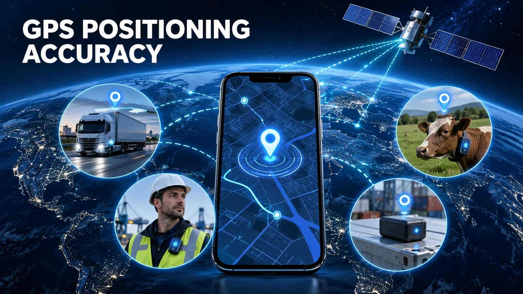
Traditional personnel tracking devices usually rely on GPS, BeiDou, or multi-constellation GNSS positioning.
These systems are sufficient for many common applications, such as:
- Determining whether personnel are inside a factory or worksite
- Detecting whether workers leave a designated area
- Reviewing historical personnel movement
- Monitoring outdoor workers
- Identifying the position of a worker who triggers an SOS alarm
However, conventional GNSS positioning is generally limited to meter-level accuracy.
For example, a standard GPS personnel badge may show that a worker is standing near a machine, while the actual position error may still be 3 meters, 5 meters, or even greater.
For routine inspection tasks, this may be acceptable.
For the following applications, however, meter-level positioning may not be precise enough:
- Personnel management around hazardous machinery
- Port operation zones
- Mining personnel monitoring
- Railway construction personnel tracking
- Power facility inspection
- Chemical plant restricted areas
- Large outdoor industrial sites
- Precise geofencing
- Work-lane identification
- High-accuracy incident reconstruction
In these environments, RTK GNSS technology can be used to improve outdoor personnel positioning from meter-level accuracy to centimeter-level or decimeter-level accuracy.
2. Design Concept of the 802 Series RTK Personnel Tracking Terminal
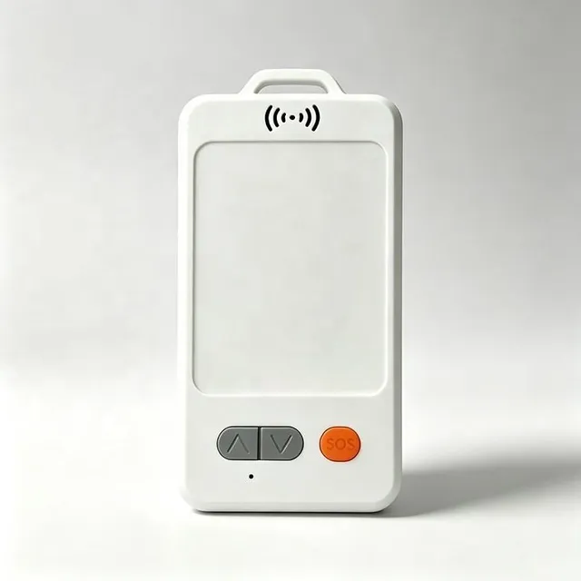
The 802 Series can be designed as a high-precision GNSS tracking terminal for industrial personnel applications.
A typical technical architecture may include:
RTK GNSS + 4G / LoRaWAN + MCU + IMU + SOS + Cloud Platform
The terminal is mainly responsible for:
- Receiving GNSS satellite signals
- Receiving RTCM correction data
- Performing RTK positioning
- Determining the current positioning status
- Uploading data through 4G or LoRaWAN
- Triggering SOS, geofence, and abnormal-event alarms
- Recording historical personnel movement
- Uploading high-precision coordinates to the server
3. 802 Series RTK Hardware Architecture
A complete RTK personnel tracking badge normally includes the following hardware modules.
3.1 RTK GNSS Module
This is the core component of the system.
It is recommended to support:
- GPS
- BDS
- Galileo
- GLONASS
- Multi-frequency GNSS
- RTCM input
- RTK Float
- RTK Fixed
- NMEA output
- High-rate positioning updates
For high-precision personnel positioning, a dual-frequency or multi-frequency RTK module such as L1 + L2 or L1 + L5 is generally preferred.
Compared with single-frequency solutions, multi-frequency GNSS can provide better:
- Convergence speed
- Resistance to multipath interference
- RTK FIX stability
- Recovery performance after signal obstruction
3.2 GNSS Antenna
Many RTK projects fail not because of the RTK chipset, but because of the antenna design.
Personnel tracking badges are usually compact, which makes GNSS antenna design more difficult.
Important factors include:
- Effective antenna area
- Antenna gain
- Human-body attenuation
- PCB dimensions
- Battery location
- Enclosure material
- Isolation from the 4G antenna
- Isolation from the LoRa antenna
For RTK products, antenna performance should not only be evaluated on a bare development board.
Testing should be performed with the complete product:
PCBA + Battery + Enclosure + Real Human Wearing Condition
4. Why Is Personnel RTK More Difficult Than Vehicle RTK?
A vehicle RTK system can place the GNSS antenna on the roof of the vehicle.
This location is usually open and provides good satellite visibility.
Personnel devices are different.
A worker is constantly:
- Walking
- Turning
- Bending down
- Moving close to buildings
- Standing beside vehicles
- Working near metal structures
The human body itself can also block part of the GNSS signal.
Therefore, the most important technical challenge for an RTK personnel badge is not simply whether it can obtain an RTK FIX.
The more important question is:
How long can the device maintain RTK FIX while the person is moving?
5. Recommended Installation Positions for the 802 Series
5.1 Shoulder Mounting
The shoulder is generally more suitable for GNSS positioning than the waist or trouser pocket.
Advantages include:
- Better sky visibility
- Less human-body obstruction
- More stable antenna orientation
5.2 Safety Helmet Mounting
If the application allows it, the GNSS antenna can be integrated into or mounted on top of a safety helmet.
This is one of the best installation methods for personnel RTK.
Advantages include:
- Higher antenna position
- Reduced human-body blockage
- Better sky visibility
- More stable RTK FIX performance
However, the design must also consider:
- Weight
- Battery placement
- Waterproofing
- Cabling
- Helmet safety certification
5.3 Chest Mounting
Chest mounting is convenient and practical.
However, human-body blockage can be significant.
When using chest mounting, it is recommended to test the device at different body orientations:
0°
90°
180°
270°
During testing, record:
- Satellite count
- C/N0
- RTK FIX rate
- Positioning accuracy
6. How the 802 Series Works with 4G RTK
When using 4G-based RTK, the data flow can be designed as follows:
Satellite Signals
↓
802 RTK Personnel Terminal
↓
4G Network
↓
NTRIP Server
↓
RTCM Correction Data Returned to the 802 Device
↓
RTK GNSS Module Performs Positioning
↓
Centimeter-Level Coordinates
↓
Position Data Uploaded to the lora8 Platform via 4G
Advantages of 4G RTK
A 4G-based architecture is suitable for projects where devices are deployed across a wide geographic area.
Typical applications include:
- Nationwide construction personnel
- Oilfield inspection workers
- Power grid inspection
- Port personnel
- Urban engineering teams
- Outdoor security personnel
As long as a 4G network is available, the terminal can connect to an NTRIP correction service.
7. 802 Series LoRaWAN RTK Architecture
For fixed sites such as industrial parks, farms, mines, or large campuses, the system can use:
RTK GNSS + LoRaWAN
Data flow:
802 RTK Personnel Terminal
↓
RTK Position Calculation
↓
LoRaWAN
↓
LoRaWAN Gateway
↓
Ethernet / 4G
↓
Server
↓
Personnel Tracking Platform
One major advantage of this architecture is that the terminal itself may not need an individual SIM card for location data transmission.
It is suitable for:
- Large numbers of workers
- Private wireless networks
- Fixed industrial sites
- SIM-free terminals
- Local private deployments
8. How Should RTCM Correction Data Be Transmitted?
There are two major data directions in an RTK system.
8.1 Position Data
The terminal uploads positioning data to the server, including:
- Latitude
- Longitude
- Altitude
- RTK status
- Satellite count
- Battery level
- SOS status
8.2 RTCM Correction Data
The server or base station sends RTCM correction data to the RTK terminal.
These two data flows must not be confused.
9. RTCM Data Forwarding Design
The 802 terminal may use the following workflow:
4G TCP Connection Established
↓
NTRIP Authentication
↓
RTCM Data Received
↓
MCU Buffering
↓
RTCM Sent to RTK GNSS Module via UART
↓
GNSS Module Performs Carrier-Phase Differential Processing
↓
RTK FIX Coordinates Generated
10. Why Is RTCM Buffer Management Important?
4G networks are not perfectly stable.
Short delays such as:
100 ms
500 ms
1 second
may occur during normal operation.
The MCU should therefore use an appropriate buffer.
However, the buffer must not be too large.
RTCM is real-time correction data.
If the GNSS module receives correction data that is already 10 seconds old, its value may be greatly reduced.
The server should therefore record:
RTCM Age
This indicates the age of the correction data.
11. Recommended RTK Position Reporting Data Format
The 802 Series should not upload only:
Latitude
Longitude
The recommended data set should include at least:
Device ID
Timestamp
Latitude
Longitude
Altitude
Speed
Heading
Fix Type
RTK Status
Satellite Count
HDOP
RTCM Age
GNSS Signal Level
Battery Level
4G RSSI
SOS Status
Motion Status
12. Why Must the Server Store RTK Status?
Suppose the server receives the following coordinates:
22.543456
114.057892
These coordinates alone do not prove that the device is operating at centimeter-level accuracy.
The position may come from:
Single GNSS
RTK Float
RTK Fixed
Therefore, the platform should display the positioning status together with the coordinates.
For example:
RTK FIX
RTK FLOAT
GNSS
Without this information, the user cannot know the actual quality of the current position.
13. How Should RTK Personnel Status Be Displayed on the Map?
The platform can use different status labels.
For example:
Device A
RTK FIX
Accuracy: 0.02 m
Device B
RTK FLOAT
Accuracy: 0.35 m
Device C
GNSS
Accuracy: 3.2 m
This allows operators to quickly understand the positioning quality of each terminal.
14. How Should RTK Geofencing Be Designed?
Conventional GPS geofences are usually not designed to be extremely small.
Common radii may be:
50 m
100 m
500 m
This is because standard GPS itself may have several meters of error.
RTK makes it possible to create much more precise geofences.
For example:
1 m
2 m
5 m
It can also be used to define a restricted area around a specific machine or work zone.
15. Hazardous Equipment Geofence Example
Suppose a factory has a hazardous machine.
A restricted area with a radius of 2 meters is created around the equipment.
The 802 personnel badge continuously calculates centimeter-level coordinates.
When a worker enters the restricted zone, the system immediately triggers:
Restricted Zone Alarm
The server can record:
Worker ID
Entry Time
Entry Position
Exit Time
Duration of Stay
16. How to Test RTK Personnel Trajectory Accuracy
The test worker wears the 802 terminal.
A predefined test route is marked on the ground.
For example:
A 100-meter straight line.
The worker walks along the same line back and forth 10 times.
The 10 recorded tracks are then overlaid.
If the system is stable:
The 10 tracks should largely overlap.
If the tracks differ by:
2 to 5 meters
the system is not yet demonstrating the real benefit of RTK.
17. RTK Circular Walking Test
Another useful test method is to mark a circle on the ground.
For example:
Radius: 5 meters.
The worker walks around the circle 10 times.
The platform records the trajectory.
Under good RTK conditions:
The 10 loops should form a highly consistent circular track.
This test is useful for identifying:
- Drift
- Position jumps
- RTK loss
- Multipath errors
18. RTK Fixed-Point Repeatability Test
Select a point with accurately known coordinates.
Ask the worker to stand at the point for 60 seconds.
Then leave the location.
Return after 5 minutes.
Repeat this process 20 times.
Record the position every time.
If the reported coordinates remain within a small centimeter-level area, the system demonstrates good repeatability.
19. Obstruction Recovery Test
This is an important test for the 802 personnel tracker.
First, the worker obtains:
RTK FIX
in an open area.
Then the worker moves under a building structure or into a partially blocked area.
Observe whether the status changes to:
RTK FLOAT
or:
GNSS
Then move back into an open area.
Measure the time from restored sky visibility until RTK FIX is recovered.
This parameter can be called:
RTK Re-Fix Time
20. 4G Network Disconnection Recovery Test
Manually disconnect the 4G network.
For example, interrupt communication for:
30 seconds.
Observe:
- Whether RTCM reception stops
- When the RTK status degrades
- Whether the device falls back to Float
- Whether the device falls back to Single GNSS
Then restore 4G.
The device should automatically:
Reconnect to the mobile network
↓
Reconnect to the NTRIP service
↓
Receive RTCM correction data again
↓
Recover RTK FIX
The entire process should not require a manual restart.
21. Weak Network Environment Testing
An RTK personnel product should also be tested under:
- Weak 4G signal
- High network latency
- Packet loss
- Cellular handover
- Elevator entrances
- Underground entrances
- Remote outdoor areas
If the network becomes unstable for a short period, the system should attempt to maintain positioning continuity as much as possible.
22. LoRaWAN RTK Personnel Testing
The LoRaWAN version should also include radio coverage testing.
Important parameters include:
RSSI
SNR
Packet Loss
Gateway Distance
Upload Success Rate
For example:
The personnel terminal uploads one position every 5 seconds.
Run the test continuously for one hour.
Count:
Total packets
Successfully received packets
Lost packets
Upload success rate
23. Battery Testing
RTK typically consumes more power than standard GNSS.
The device may need to operate:
GNSS continuously
RTK processing continuously
Wireless communication
Sensors
MCU processing
Therefore, battery performance should not be evaluated only by battery capacity.
Real operating modes should be tested.
Mode 1: Real-Time RTK
For example:
GNSS always on
1 Hz positioning
Data upload every 5 seconds
This mode provides the highest real-time performance but also consumes the most power.
Mode 2: Intelligent RTK
When the worker is moving:
Use high-frequency RTK.
When the worker is stationary:
Reduce positioning frequency.
This approach can significantly reduce power consumption.
24. Why Should an IMU Be Added to the 802 Series?
RTK performs very well in open environments.
However, when a person temporarily enters a partially blocked area, GNSS performance may degrade.
By adding:
- Accelerometer
- Gyroscope
- Six-axis IMU
the system can support:
- Motion detection
- Fall detection
- Stationary detection
- Step counting
- Short-term inertial assistance
The system can also be extended to:
GNSS + IMU sensor fusion.
25. RTK + IMU Fusion Positioning
In a sensor fusion system:
GNSS provides the absolute position.
The IMU provides:
- Acceleration
- Orientation
- Short-term movement estimation
When GNSS is temporarily obstructed:
The IMU can continue to provide movement information.
When GNSS becomes available again:
The system can correct the position.
This can improve trajectory continuity.
26. SOS Function in an RTK Personnel Tracking System
The 802 Series can include a dedicated SOS button.
When the worker presses the SOS button, the device can immediately upload:
SOS Alarm
Device ID
Worker Name
Latitude
Longitude
RTK Status
Alarm Time
Battery Level
The server can then display:
SOS EMERGENCY
and show the worker's location on the map.
27. Man-Down or Long-Inactivity Alarm
By using the IMU, the device can determine whether the worker has remained motionless for an unusually long period.
For example:
No movement for more than 10 minutes.
The system can treat this as a potential abnormal event.
This feature is useful for:
- Mining
- Lone workers
- Night inspection
- High-risk maintenance tasks
28. Fall Detection
A six-axis sensor can be used to support:
Fall Detection
A typical detection logic may include:
Sudden acceleration
↓
Orientation change
↓
Continuous inactivity
↓
Fall alarm triggered
However, fall detection should not rely only on a single acceleration threshold.
Otherwise, false alarms can occur.
29. Recommended Backend Functions for the 802 Series
The platform can include the following major sections.
Monitoring Center
Real-time personnel monitoring.
Display:
- Worker
- Device
- Online status
- RTK status
- Map position
History Playback
Historical track playback.
Support:
- Time selection
- Track playback
- Stop points
- Alarm points
Geofence
Electronic geofence management.
Support:
- Circular fences
- Polygon fences
- High-risk areas
- Restricted zones
Alarm Center
Display:
- SOS alarms
- Geofence entry alarms
- Geofence exit alarms
- Low battery alarms
- Fall alarms
- Long inactivity alarms
- Device offline alarms
30. RTK System Validation Should Not Be Based on a Single Test
A real industrial RTK project should be tested in several stages.
Stage 1: Laboratory Testing
Test:
RTK module
RTCM
Server
Communication
Stage 2: Open-Sky Outdoor Testing
Evaluate the best possible RTK performance.
Stage 3: Real Human Wearing Test
Evaluate the influence of the human body on antenna performance.
Stage 4: Industrial Site Testing
Evaluate performance near:
Buildings
Vehicles
Metal structures
Industrial equipment
Stage 5: Long-Term Testing
Continuous operation should be tested for:
24 hours
72 hours
7 days
or even 30 days.
31. Recommended RTK Automatic Test Reports
The server can generate daily statistics such as:
Total device online time
RTK FIX duration
RTK FLOAT duration
Standard GNSS duration
No-position duration
Average satellite count
Minimum satellite count
Average HDOP
Maximum RTCM age
Number of network disconnections
Number of RTK re-fixes
32. How to Calculate RTK FIX Rate
A useful metric is:
RTK FIX Rate
Formula:
RTK FIX Time ÷ Valid GNSS Positioning Time × 100%
For example:
The device operates for 10 hours.
RTK FIX: 8.5 hours
RTK FLOAT: 1 hour
GNSS: 0.5 hour
RTK FIX Rate:
85%
This metric is often more meaningful than simply claiming:
“Centimeter-Level Positioning Supported.”
33. Stability Matters More Than a Single Best Accuracy Result
A device may achieve:
1 cm accuracy
in an ideal open environment.
However, if it frequently drops to Float after a few minutes, the real-world user experience may still be poor.
Another device may consistently maintain:
2 to 3 cm accuracy
while staying in RTK FIX for a much longer period.
For industrial applications, the second system may provide more practical value.
Therefore, an RTK project should evaluate:
- Accuracy
- Time to FIX
- FIX retention rate
- Obstruction recovery
- Network recovery
- Long-term operating stability
34. Typical Applications of the 802 Series
Industrial Personnel Tracking
High-accuracy worker tracking in factories and industrial sites.
Construction Worker Tracking
Personnel monitoring on construction sites.
Mining Personnel Tracking
Outdoor mining personnel location management.
Port Worker Tracking
High-precision worker tracking in ports and logistics yards.
Oil & Gas Worker Tracking
Personnel tracking for oilfields and energy facilities.
Railway Worker Tracking
Position monitoring for railway construction and maintenance teams.
Outdoor Lone Worker Tracking
High-accuracy location monitoring for lone workers operating outdoors.
35. Advantages of Combining RTK with LoRaWAN
For fixed industrial sites with a large number of users:
If every device uses an independent 4G SIM card, communication costs can become significant.
With LoRaWAN:
Personnel Device
↓
LoRaWAN
↓
One or More Gateways
↓
Internet
↓
Platform
the terminal can reduce or eliminate its dependence on a SIM card.
This is especially suitable for deployments involving:
500 workers
1,000 workers
5,000 workers
or even larger projects.
36. 4G + LoRaWAN Dual-Communication Design
A more advanced 802 version can support:
4G + LoRaWAN Dual Communication
Under normal conditions:
Use LoRaWAN.
When the LoRa network is unavailable:
Switch to 4G.
This architecture can improve communication reliability in industrial environments.
37. Centimeter-Level Positioning Does Not Mean Centimeter-Level Accuracy Everywhere
This point should be clearly stated in technical documentation.
RTK centimeter-level accuracy normally requires:
- Good satellite visibility
- Valid RTCM correction data
- Appropriate base-station distance
- Good GNSS antenna performance
- RTK FIX status
If personnel enter:
Basements
Indoor buildings
Tunnels
Large metal structures
GNSS performance will be significantly reduced.
Therefore, it is not professional to claim:
“Centimeter-level accuracy in every environment.”
A more accurate statement is:
Centimeter-level positioning can be achieved in open-sky environments when the terminal maintains RTK FIX status.
38. Indoor and Outdoor Hybrid Positioning
For a complete personnel positioning project, the system can use:
Outdoor
RTK GNSS
Semi-Outdoor
RTK GNSS + IMU
Indoor
Bluetooth
or:
UWB
The server can automatically identify the current positioning source.
All location data can then be displayed on the same management platform.
39. Recommended Software Architecture for the 802 Series
Device Layer:
802 RTK Personnel Tracker
Communication Layer:
4G / LoRaWAN
Positioning Layer:
GNSS + RTK + IMU
Protocol Layer:
TCP / UDP / MQTT
Platform Layer:
lora8 IoT Platform
Application Layer:
Web + Android + iOS + API
40. Server Deployment
If the customer requires private deployment, the system can be installed on the customer's own infrastructure.
Typical architecture:
Customer Server
↓
Linux
↓
Device Server
↓
Database
↓
Redis
↓
RTK Data Processing
↓
Web Platform
This allows customers to keep their personnel tracking data within their own private environment.
41. Final RTK Personnel Tracking Project Test Checklist
Before project delivery, the following metrics should be tested:
Positioning Success Rate
RTK FIX Rate
Time to First Position
Time to First RTK FIX
Horizontal Accuracy
Vertical Accuracy
Static Drift
Dynamic Track Error
Obstruction Recovery Time
NTRIP Reconnection Time
4G Reconnection Time
LoRaWAN Upload Success Rate
Battery Life
SOS Response Time
Geofence Alarm Delay
Platform Data Latency
42. The Real Technical Challenge of an RTK Personnel Tracking Product
An RTK product is not simply:
Buying an RTK GNSS module
Adding a 4G communication module
A production-ready system requires complete system engineering.
This includes:
GNSS RF design
Antenna design
PCB layout
EMC design
Low-power design
RTCM transmission
NTRIP integration
4G communication stability
LoRaWAN communication
RTK status management
Cloud platform development
Mapping
Historical trajectory processing
Geofencing
OTA updates
Field testing
Only when all of these components are fully integrated can an RTK terminal move from a laboratory prototype to a reliable industrial product.
43. Conclusion
The core value of the 802 Series RTK high-precision personnel tracking device is to upgrade conventional outdoor GPS personnel tracking from meter-level positioning to significantly higher accuracy.
By combining:
RTK GNSS + 4G / LoRaWAN + IMU + SOS + Cloud Platform
the system can provide a complete high-precision personnel tracking solution covering the device, wireless communication, correction service, and backend management platform.
When evaluating an RTK personnel tracking product, users should not focus only on marketing claims such as:
“1 cm accuracy”
or:
“2 cm accuracy.”
More important indicators include:
RTK FIX rate, time to first FIX, dynamic trajectory stability, human-body obstruction effects, network recovery capability, RTCM latency, long-term operating stability, and real-world field performance.
For industrial personnel positioning, the real value is not achieving centimeter-level accuracy during one ideal test.
The real value is the ability to operate reliably in actual working environments while integrating high-precision positioning, personnel alarms, geofencing, historical tracking, and platform management into one complete system.
That is what defines a practical, deployable RTK high-precision personnel tracking solution.