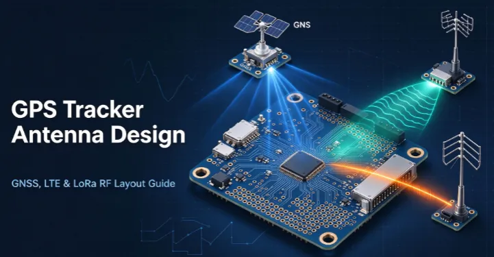
GPS tracker antenna design is one of the most critical PCB RF design tasks for modern IoT tracking devices. A typical asset tracker integrates three core wireless systems:GNSS for satellite positioning, LTE for cellular data uplink, and LoRa for long-range low-power communication. Poor RF layout and antenna isolation commonly cause GNSS desensitization, short LoRa range, unstable LTE signals, and low positioning accuracy.
This professional RF layout guide explains step-by-step GPS tracker antenna design rules for GNSS, LTE, and LoRa subsystems, covering antenna selection, PCB layout constraints, ground plane design, multi-RF interference mitigation, and testing standards for production-ready tracker hardware.
1. Key Design Challenges for Multi-RF GPS Tracker Antennas
Most GPS trackers fail in real-world environments not due to module quality, but due to multi-RF coexistence interference. Each antenna system has conflicting signal characteristics and sensitivity requirements, creating unique layout challenges:
- GNSS: Extremely weak satellite receiving signals, highly sensitive to noise and desensitization
- LTE: High-power broadband transceiver, the main source of harmonic and spurious interference
- LoRa: Narrowband low-power signals, easily overwhelmed by LTE and digital circuit noise
- Compact tracker enclosures further limit antenna spacing, ground plane size, and routing space. Proper RF layout prioritization and isolation is essential for reliable positioning and communication performance.
2. GNSS Antenna Design & RF Layout Guidelines
GNSS antenna performance directly determines tracker positioning accuracy, cold-start speed, and indoor/outdoor availability. As a pure receive-only weak-signal system, GNSS has the highest layout priority in GPS tracker design.
2.1 GNSS Antenna Selection Criteria
Choose GNSS antennas based on polarization, axial ratio, gain, and application scenarios:
- RHCP polarization: Right-Hand Circular Polarization is mandatory to avoid signal fading from device rotation
- Low axial ratio (<3dB): Ensures stable multi-constellation reception (GPS, Beidou, GLONASS, Galileo)
- Active vs passive: Passive patch antennas for cost-sensitive trackers; active GNSS antennas with built-in LNA for industrial weak-signal environments
- Recommended ground plane: 50×50mm to 70×70mm continuous copper for optimal resonance and gain
2.2 GNSS PCB Layout Best Practices
- Edge/corner placement: Place GNSS antenna at PCB top edge or corner for maximum sky view and minimal metal obstruction
- Keep-out zone: Reserve 3–5mm clear zone around the antenna pad without copper, traces, or components
- Short and straight RF traces: Minimize trace length; use 45° bends only, avoid right-angle turns
- Strict 50Ω impedance control: Uniform trace width, no sudden impedance changes
- Few vias as possible: Avoid vias on GNSS signal traces; use clustered grounding vias if necessary
- Max RF isolation: Maintain ≥15mm distance from LTE and LoRa antennas to avoid intermodulation interference
3. LTE Antenna Design & RF Layout Best Practices
LTE antennas handle high-power cellular data transmission for real-time location uploads. In multi-RF trackers, LTE is theprimary interference source that desensitizes GNSS receivers. LTE layout focuses on interference suppression and out-of-band harmonic filtering.
3.1 LTE Antenna Selection Requirements
- Full-band coverage: Support mainstream LTE bands (B1/B3/B5/B7/B8/B20) for global compatibility
- High radiation efficiency: Ensure stable uplink power in weak signal areas
- Compact form factor: FPC or chip antennas preferred for small tracker PCBs
- Low spurious emission: Suppress harmonics falling into GNSS 1550–1600MHz band
3.2 LTE PCB Layout Rules
- Opposite-corner placement: Place LTE antenna diagonally opposite the GNSS antenna for maximum physical isolation (min 10–15mm)
- Independent RF routing: Never parallel LTE transmit traces with GNSS/LoRa receive traces
- Ground isolation fences: Add grounded copper barriers between different RF channels to reduce crosstalk
- Front-end filtering: Deploy SAW filters and low-pass filters to eliminate out-of-band harmonics
- Independent power filtering: Isolate LTE power rails from GNSS/LoRa power domains to block noise coupling
4. LoRa Antenna Design & RF Layout Guidelines
LoRa antennas support long-range, low-power IoT communication for offline data logging and regional mesh networking. LoRa narrowband signals are sensitive to broadband noise, making clean layout and stable impedance critical for communication range and sensitivity.
4.1 LoRa Antenna Key Specifications
- ISM band matching: Strictly match regional frequencies (CN470MHz, EU868MHz, US915MHz)
- Low VSWR (<1.5): Minimize signal reflection and transmission loss
- Standard 50Ω impedance: Consistent impedance across the entire RF link
4.2 LoRa PCB Layout Standards
- Edge placement: Position LoRa antenna at PCB edge, far from LTE high-power radiation zones and MCU high-speed clocks
- Short trace length: Control RF trace length within 50mm to reduce insertion loss
- Solid ground connection: Use thick copper and dense grounding vias for stable ground potential
- Noise isolation: Avoid proximity to switching power circuits, large capacitors, and digital high-speed lines
5. Multi-RF Co-Design & Interference Mitigation Strategy
The biggest challenge in GPS tracker antenna design is multi-system coexistence. Isolated single-antenna layout is not enough; system-level optimization is required to eliminate desensitization and crosstalk.
5.1 Physical Isolation Layout Principle
Adopt the three-corner dispersion layout for GNSS, LTE, and LoRa antennas. Place each antenna at an independent PCB corner to maximize spatial isolation. Maintain a minimum 10mm gap between any two RF antennas to suppress near-field coupling interference. Avoid vertical stacking of different antennas on top/bottom PCB layers.
5.2 Frequency-Domain Interference Suppression
LTE transmission harmonics often fall into the GNSS L1 band, causing positioning failure. Solve this by adding GNSS band-pass filters at the receiver front-end and LTE low-pass filters at the transmitter end. Optimize antenna matching circuits to improve out-of-band suppression and reduce adjacent-band crosstalk between LTE and LoRa.
5.3 Time-Domain Staggered Working Mechanism
Implement time-division multiplexing for RF systems: pause GNSS scanning or LoRa transmission during LTE high-power uploads, and disable LTE transmission during high-precision GNSS positioning. This software-hardware coordination eliminates instantaneous co-channel interference.
6. Ground Plane & 50Ω Impedance Matching Rules
Ground plane integrity and precise impedance control determine the final RF performance of all three antenna systems, directly affecting tracker stability and communication quality.
6.1 Ground Plane Design Rules
- Reserve complete continuous ground planes as RF reference layers; avoid slotting, cutting or hollowing
- No digital or power traces pass under RF routing areas
- Dense grounding vias for antenna pads to reduce grounding impedance
6.2 50Ω Controlled Impedance Layout
All GNSS, LTE, and LoRa RF traces must follow strict 50Ω impedance design based on PCB stack-up parameters. For standard 4-layer PCBs, use 0.18–0.22mm line width with 0.2mm dielectric thickness to achieve accurate impedance.
Avoid all impedance mutations. Control total link loss within 1.5dB for GNSS receiving paths and within 2dB for LTE/LoRa transceiving paths to ensure optimal signal integrity.
7. Testing & Common RF Design Troubleshooting
Verify antenna and layout performance with standardized RF testing to fix common tracker hardware issues in mass production.
7.1 Core Test Metrics
- GNSS: Cold start time, positioning success rate, reception sensitivity, interference suppression
- LTE: Transmit power stability, receiver sensitivity, harmonic spurious level
- LoRa: Communication distance, packet loss rate, anti-interference sensitivity
7.2 Common Issues & Fixes
- Slow GNSS positioning: Caused by LTE interference or incomplete ground planes — increase isolation and add front-end filters
- Short LoRa range: Caused by impedance mismatch and noise coupling — recalibrate matching circuits and strengthen isolation
- Unstable LTE signal: Caused by long traces and poor grounding — shorten RF lines and densify grounding vias
8. Conclusion
Professional GPS tracker antenna design requires hierarchical optimization for GNSS, LTE, and LoRa RF subsystems. The core layout strategy is to prioritize weak GNSS signal protection, suppress LTE high-power interference, and stabilize LoRa narrowband communication via standardized impedance control, physical isolation, and frequency filtering.
Following these RF layout guidelines eliminates common tracker failures including poor positioning, unstable cellular connection, and short LoRa transmission distance, delivering reliable, industrial-grade GPS tracker performance for vehicle tracking, asset management, and IoT positioning applications.
Recommend High-Quality 2027 Best GPS Trackers on WeChat GPS
RTK GNSS Personnel Tracking Badge