Hardware & PCB design
PCB, enclosure, connectors, antenna and power design are reviewed against the installation and operating requirements.

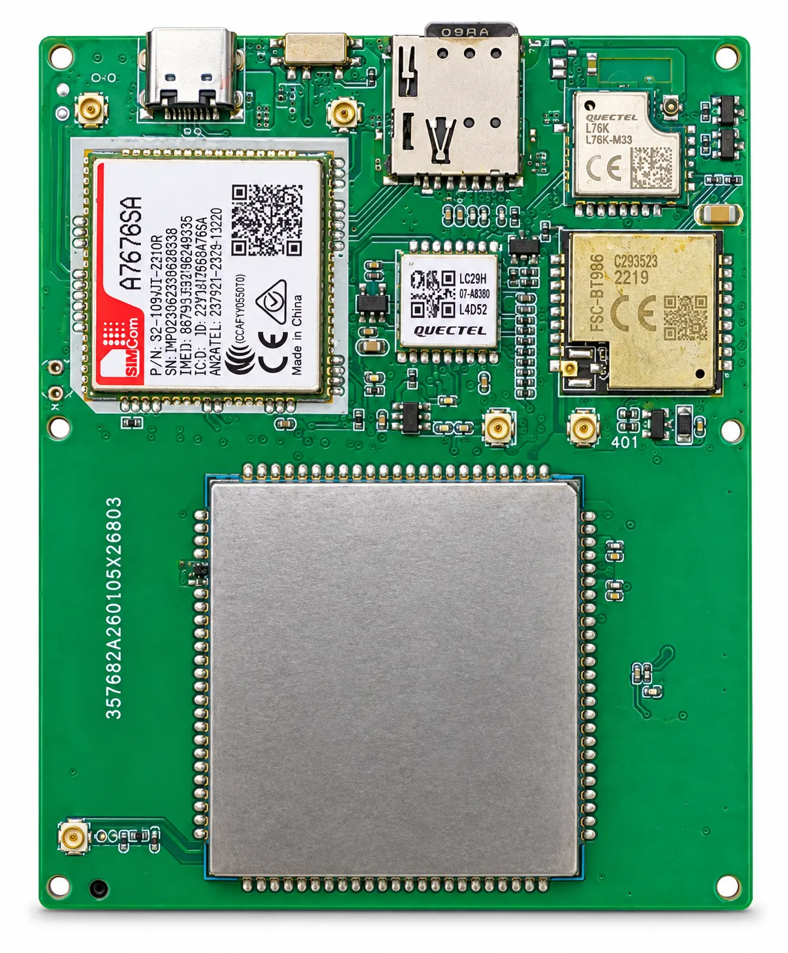
Satellite GNSS Tracker PCB Design is a customized hardware-development service combining GNSS positioning, direct satellite communication, power management, antenna integration and optional terrestrial communication on one compact PCBA. The design can support satellite communication without a conventional cellular SIM card. Optional LoRa, 4G and 2G modules can also be integrated for hybrid tracking applications that require automatic communication switching. Shenzhen Jinshengchang Technology provides schematic design, PCB layout, component selection, embedded firmware, antenna tuning, communication protocol development, prototype production, testing and mass-production support.
Final pricing depends on configuration, quantity, taxes and shipping.
Sample availability, quantity and lead time depend on the selected model. Confirm the pilot scope before placing a production order.
Satellite GNSS Tracker PCB Design is intended for companies developing tracking devices that must operate in remote regions where conventional mobile networks are unavailable or unreliable. The design combines GNSS positioning with direct satellite communication and can optionally integrate LoRa, 4G and 2G connectivity.
GNSS and satellite communication serve different purposes. The GNSS receiver obtains coordinates from navigation satellites such as GPS, BDS, GLONASS or Galileo. The communication module then sends those coordinates and device data through a communication satellite, LoRa gateway or cellular network.
When the tracker operates in satellite-only mode, it does not require a conventional cellular SIM card. However, the selected satellite network may require device activation, a registered terminal identity and a satellite messaging plan. This information should be confirmed during the early project-design stage.
A hybrid PCBA can use different networks according to the installation environment. Cellular communication can provide frequent reporting in populated areas. LoRa can provide low-power communication inside a privately deployed network. Satellite communication can act as the primary channel or as a backup when the device leaves cellular and LoRa coverage.
The hardware design must consider the higher current peaks that may occur during satellite transmission. The power supply, battery, voltage regulator, capacitors and PCB traces must be designed to keep the system stable during communication. Low-power firmware is equally important because unnecessary satellite searches or repeated transmissions can quickly reduce battery life.
RF layout and antenna integration are critical parts of the project. The GNSS receiver must detect extremely weak navigation signals, while satellite, cellular and LoRa transmitters can generate stronger RF energy. Proper component placement, grounding, shielding, filtering and antenna separation help reduce interference and improve communication reliability.
Shenzhen Jinshengchang Technology provides schematic design, PCB layout, embedded firmware, communication protocol development, antenna tuning, prototype production and OEM manufacturing. The tracking platform can display real-time locations, historical routes, geofences, alarms, battery status and network information.
With 13 years of GPS research and development experience, our engineering team can develop satellite GNSS tracker PCB solutions for vehicles, boats, containers, industrial assets, outdoor personnel and livestock. Each PCBA can be customized according to the required satellite network, communication modes, dimensions, interfaces, power source and deployment environment.
Reference configurations are shown below. Final specifications are confirmed in the approved product specification.
| Product Type | Custom satellite GNSS tracker PCB or assembled PCBA. |
|---|---|
| Positioning | GPS, BDS, GLONASS and Galileo options. |
| Primary Communication | Direct satellite communication. |
| Optional Communication | LoRa, LoRaWAN, 4G LTE, LTE Cat 1, LTE-M, NB-IoT or 2G. |
| Cellular SIM Card | Not required for satellite-only operation. |
| Satellite Activation | A compatible satellite network account or service plan may be required. |
| Communication Direction | One-way or two-way communication, depending on the selected satellite network. |
| Processor | Low-power MCU or integrated communication processor. |
| PCB Structure | Two-layer, four-layer or multilayer PCB according to size and RF requirements. |
| Power Supply | Rechargeable battery, primary lithium battery, vehicle power or solar power. |
| Power Management | Deep sleep, timed wake-up, motion wake-up and adaptive reporting. |
| Tracking Modes | Scheduled, motion-based, real-time and emergency tracking. |
| Sensors | Accelerometer, temperature sensor, light sensor and Hall sensor options. |
| Interfaces | UART, I²C, SPI, ADC, GPIO, USB, RS232, RS485 or CAN. |
| Data Storage | Local flash memory for offline location and event records. |
| Alarm Functions | SOS, geofence, movement, tamper, low battery and communication-failure alarms. |
| Antenna Options | Integrated or external GNSS, satellite, LoRa and cellular antennas. |
| Communication Protocol | MQTT, TCP, UDP, HTTP, HTTPS or customized private protocol. |
| Platform Access | Web platform, Android APP, iOS APP and API. |
| Firmware Upgrade | Local upgrade or remote FOTA when supported by the network. |
| Customization | PCB dimensions, components, firmware, protocol, interfaces, antennas and enclosure. |
| Satellite Mode | Transmits GNSS locations directly through the selected satellite network. |
| LoRa Mode | Provides low-power local communication through a private LoRa or LoRaWAN network. |
| 4G Mode | Supports frequent data transmission in areas with cellular-network coverage. |
| 2G Mode | Can be retained for target markets where compatible GSM networks remain available. |
| Hybrid Mode | Selects the appropriate communication channel according to coverage, power consumption and operating cost. |
| Emergency Mode | Prioritizes satellite communication when cellular and LoRa networks are unavailable. |
| Offline Mode | Stores location records locally until a communication channel becomes available. |
| GNSS Receiver | Calculates the tracker’s position, speed, direction and time. |
| Satellite Module | Sends location and alarm data through a supported satellite network. |
| LoRa Module | Connects the tracker to a nearby LoRa gateway when private network coverage is available. |
| Cellular Module | Uses 4G or 2G communication in supported service areas. |
| Low-Power MCU | Controls positioning, communication, sensors, data storage and power states. |
| Power-Management Circuit | Manages the battery, charging, voltage regulation and system protection. |
| Sensor Interfaces | Connect motion, temperature, tamper and other optional sensors. |
| Tracking Platform | Receives, stores and displays location, alarm and device-status data. |
| API Interface | Connects the tracker with the customer’s existing fleet, asset or IoT platform. |
Confirm satellite-network coverage in the intended operating region.
Activate the satellite device identity and service account before deployment.
Configure LoRa, 4G or 2G communication parameters when those networks are included.
Register each device ID on the tracking platform.
Configure positioning intervals, communication priorities and alarm rules.
Install the antenna in a position with a suitable view of the sky.
Avoid placing satellite and GNSS antennas beneath thick metal covers.
Use an external antenna when the device is installed inside a metal vehicle or enclosure.
Test satellite communication at the final installation location.
Verify that location data and alarms are displayed correctly on the platform.
Adjust reporting intervals to balance battery life, communication cost and tracking frequency.
Inspect the waterproof enclosure and cable connections before long-term outdoor deployment.
Define the application, country, quantity, reporting interval and target battery life.
Agree the device, network, power system, payload and platform interfaces.
Test representative devices, coverage, power consumption and alarm delivery on site.
Approve the specification and pilot results, then plan production, installation and support.
PCB, enclosure, connectors, antenna and power design are reviewed against the installation and operating requirements.
Reporting intervals, event logic, payload encoding and remote configuration are defined in a versioned interface document.
Device registration, maps, history, alarms and customer APIs are scoped together with access permissions and data handling.
Logo, enclosure color, labels, packaging and white-label interfaces can be assessed for the selected product and order quantity.
Sample availability, quantity and lead time depend on the selected model. Confirm the pilot scope before placing a production order.
Logo, packaging, firmware, payloads and API integration can be assessed within the agreed OEM / ODM scope.
Reporting interval, installation, radio conditions and temperature affect results. Confirm the operating profile and validate it during the pilot.
Share the country, device quantity, application, network, power target and platform requirements. Include drawings or interface documents when available.
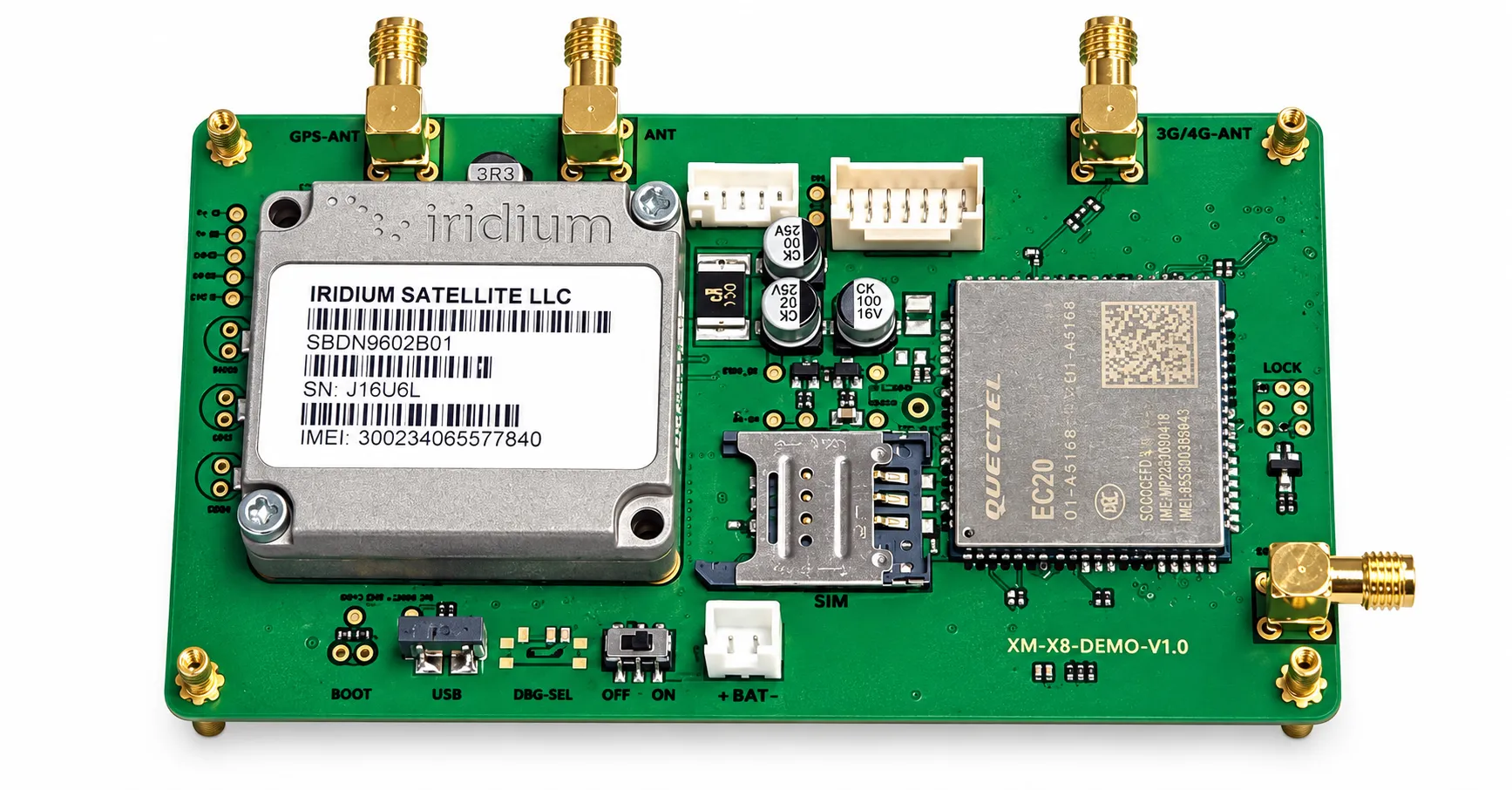
The Direct-to-Satellite GPS Tracker combines GNSS positioning with satellite data communication to track vehicles, boats, containers, equipment, personnel and animals in areas without cellular coverage. Location and alarm data can be transmitted directly to a supported satellite network without relying on a conventional 2G, 3G or 4G base station. The device does not require a conventional cellular SIM card, but satellite network activation, a device identity and a satellite service plan may still be required. Shenzhen Jinshengchang Technology provides customized hardware, satellite-module integration, low-power PCBA design, embedded firmware, antenna development, tracking platform, API integration, prototype production and OEM manufacturing.